Designing the model.


I had a few idea about what I wanted to do this week, but since I'm still pretty new with cad softwares and wood is expensive I decide to try to make something not so big for my first try with milling wood with our brand new CNC. 
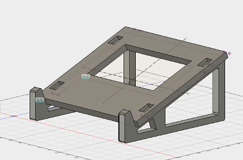
So I try to design a stand for my laptop.

I must say my design was heavily influenced by the autodesk fusion 360 tutorial found here . I learn a lot during this tutorial and after watching it, made my own laptopstand who fits with my laptop, my materials and my esthetic taste.

CAD

I'm starting to really enjoy working with Fusion 360, there are still some things I find weird with the software but it's a really nice tool in it's whole.

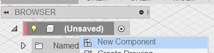
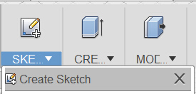
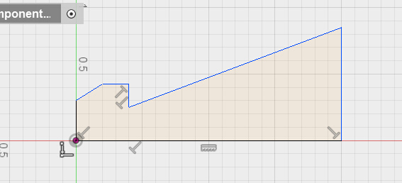
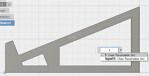
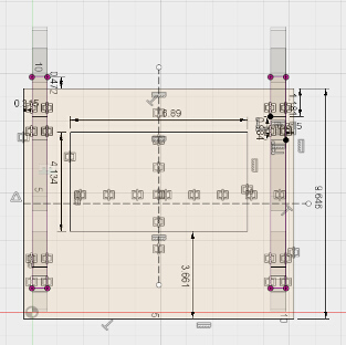
So my first step was to sketch the legs of my stand and attribute their constraints and dimension. To do so In my new fusion file I created a new component and then a new sketch inside this component.


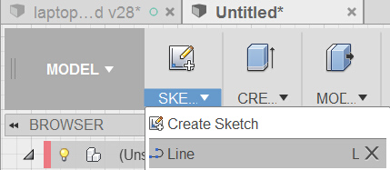
Then I used the line tool to draw an approximative shape of my leg stand.


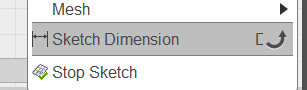
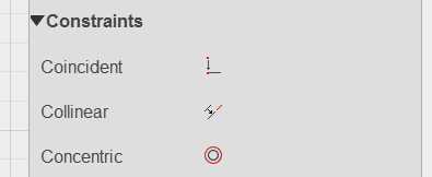
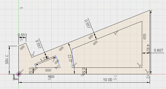
All I had left to do was to add the dimensions and constraint to properly shape the leg like I wanted to. Using the dimension tool and the sketch palette for my constrait.


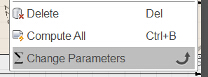
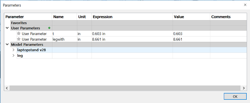
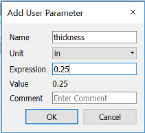
Before I write about the extrusion, let me talk about a really nice function I used for this design, wich is the changes parameters function, this is a real neat feature that give you the possibilities to create parameters for your model, like the thickness of your material so if it's ever change, you only need to change this parameters instead of every measure of the design.


So now that my parameters are set, I can now extrude my sketch using the extrude function and selecting only the part I want to extrude.


And as you can see, I use the function thickness for my extrude offset, this is the parameters I just set inside my change parameters function, so no if I change this parameters, the design will change as well.

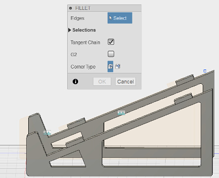
After that, I made the sketch for the top part of my stand using the same process (aproximative sketch, dimension and constraint, extrude, filet)


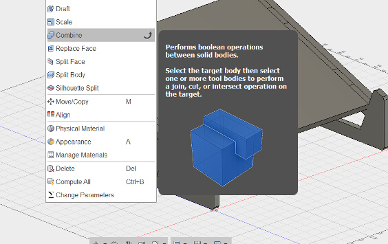
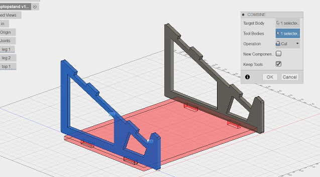
Once my top stand was place on top of my legs, I use the combine function to dig the leg so it can fit inside the top part.


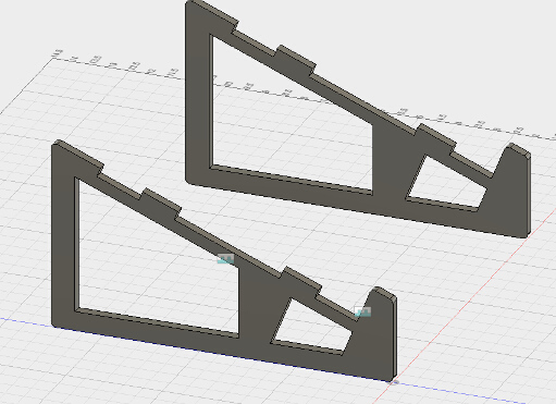
I then copy and paste the component so I can have two legs that are exactly the same and can be modified at the same time. Once the extrude was done I use the filet function to applied smooth my corner. 
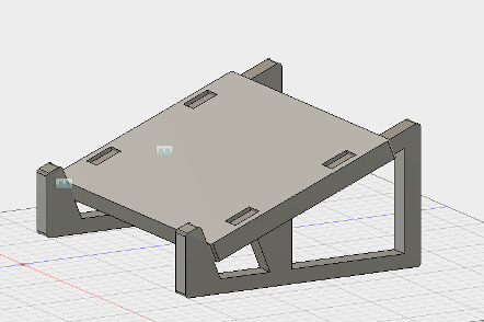
Then I designed the top of the stand by creating a new component and a new sketch inside of it.


Here we go, my CAD is done!

milling the part


We just got a brand new CNC that we put into an other lab since we don't have the place here at echofab This brand new toy as a working space of 4 by 8 feet! We are super happy to be able to use such a large machine and the possibility are now endless, here is a photo of the beast!


The machine is a SMX 4896 It is a really neat stepper CNC that has a vacum integraded to hold the plank without clamping, it has a maximum feedrate speed of 25kmm/min and a working dimension of 4'/8'. First thing first I had to do was to bring my CAD design into a Gcode so what I did is made a drawing from my design with Fusion and export it as a PDF to Inkscape.


Then I import this svg file inside my cam software wich is WINPCSIGN CNC , this is the software that comes with our machine and it's actually pretty cool and straight forward.


For my milling I use a 6mm mill


So I went inside the toolbox of the software to find the good mill that has preset parameters.


Once my tool was set I then generate the path and set it as an outside cut.


Everythings is set so I generate a Gcode and put into a usb key. Next I need to get ready my machine, First thing I did was to start the vacum bed on the machine, this awsome feature suck up your material on the bed so you dont need any kind of clamp or screws to fix your material on the bed.


I can see the pressure that is done to my surface with this gauge. I can open and close different part of the bed depending on the surface I need for my cut.


After that I home my machine by using the command on the remote and placing my bit on the edge of my plank, then I just press x/y homing, for the Z homing I use the automatic homing that comes with the machine. and lauch the job, it goes really fast and I realized too late that I forgot to set my material thickness so the cut didn't pass all the way trough my plywood. I just reset the parameters and lauch the job again, the machine made a really nice job and I was super happy to see my design comes to reality. Once it was out of the machine I realise I made quite a few mistake with the design, I design the wole thing like if the CNC was just a huge laser cutter, wich is not (I did not use any margin and did'nt do any test before hand. the pressfit was way too tight and I had to pass with sand paper to make the part fits, I think I should have used a dog bone technique to fits my parts.


Even if it's far from perfect, it works and I'm pretty happy with the result, I'll go back to the machine this fryday to see if I can make another little something cause I really want to get good with the machine. I'll uplaud the website as soon as it's done!

My file!

« Go back to assigments page